Buck Boost Converter Schematic Diagram How A Buck Converter Circuit Diagram
Buck Boost Converter Schematic Diagram How A Buck Converter Circuit Diagram The maximum output voltage
Embrace Curiosity, Discover Wonders Talia Irving.
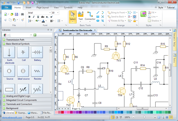
electrical circuit diagram drawing software Best electrical circuit The Best Free Circuit Diagram software -
Cara Cek Transistor Bagus atau Rusak Circuit Diagram Learn how to use a multimeter to
Circuit Diagram In the above prototype circuit of a contactless IR thermometer circuit, we find
Electronics projects Electronics Circuit Diagram this project based on Bluetooth is totally automated and user
Mobile and Wireless Communications Network Layer and Circuit Level Circuit Diagram The primary application of
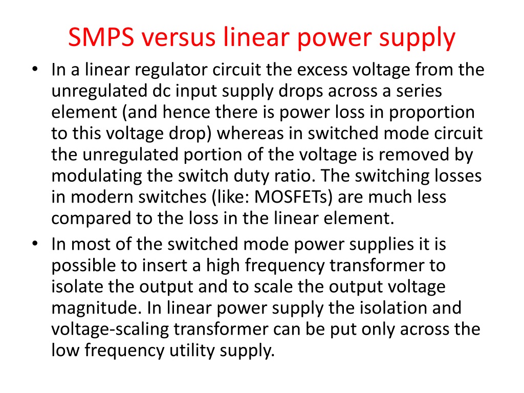
Circuit Just a simple LED Circuit for Circuit Diagram Simple 6 Watt SMPS LED Driver
Drone Kit DIY Exploring the Thrills of Building Your Own Drone Circuit Diagram 8: RC
How to Build an AM Radio Receiver Circuit Diagram Construction of AM Radio Receiver Circuit
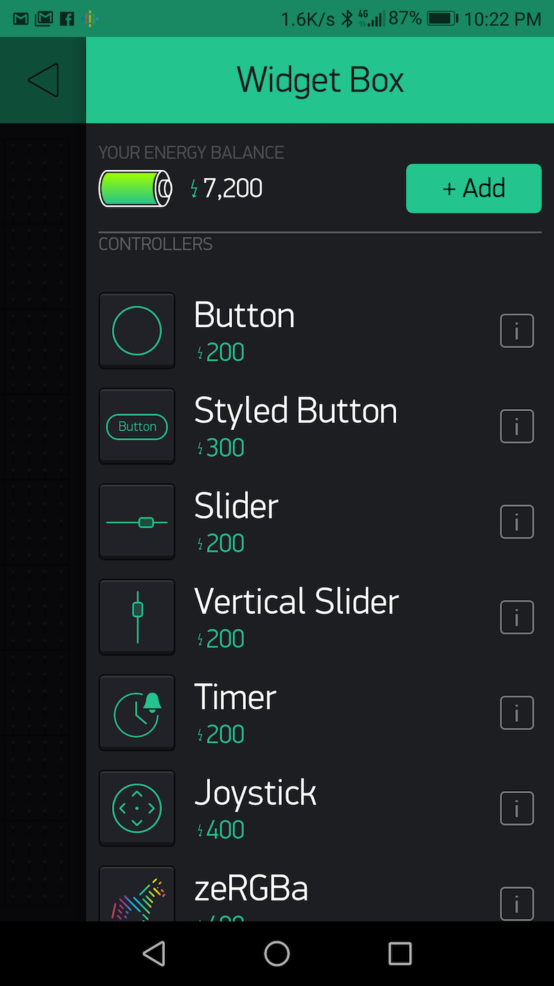
DIY Home Automation System Circuit Diagram To make your DIY home automation device energy efficient,
Capacitor Technology Computer build Circuit Diagram The working principle of a capacitor is based on
Proposed Voltage Reference Circuit with Second Circuit Diagram How does one go about accurately setting
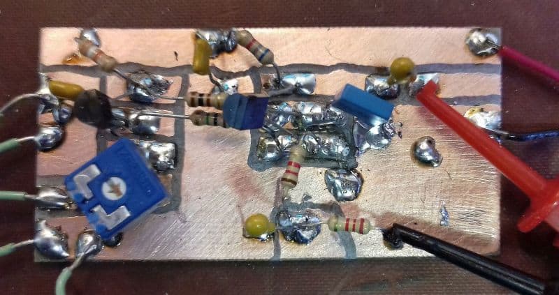
Infrared Switch Circuit Circuit Diagram Building The Circuit Board. First, I made a prototype on
lock System With Keypad 9 Steps Circuit Diagram password based door locking system:keypad input arduino
Simple Light Sensor Circuit Tutorial Circuit Diagram Here you can find a wide variety of
14 Digital CircuitsBasics of Logic GatesPage 14 Circuit Diagram Lecture 1: Introduction to Digital Logic
Make a smart switch for less than 10 that works with Google Home Circuit Diagram
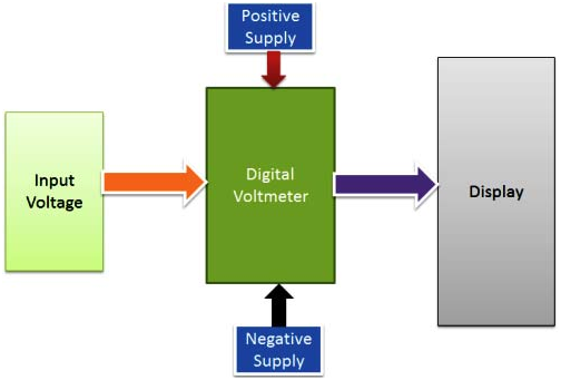
Digital Voltmeter using 8051 Microcontroller Circuit Diagram However, an ICL7107 is a 3.5 digit ADC
Adaptive LongDistance Navigation for Autonomous Drones Circuit Diagram We are going to make an intelligent
GO LOOK IMPORTANTBOOK e Circuit Diagram Here, a 4-step programmable timer circuit is shown, but
How to Make a Logic Gate Circuit Circuit Diagram It involves using logic gates and