Realtime 3D Circuit Simulation Circuit Diagram
Realtime 3D Circuit Simulation Circuit Diagram CRUMB is an immersive interactive 3D circuit simulator that
Wander Everywhere, Find Inspiration Talia Irving.
How to Read and Understand Basic Electronic Electric Circuit Diagrams An electrical schematic is a
How To Make A Arduino Home Automation System Circuit Diagram In this Arduino project, we
Broken Trace Repair electronics technology Circuit Diagram How to repair damaged / broken PCB traces
Transforming your Raspberry PI into a simple voice assistant Circuit Diagram Transform your Raspberry Pi
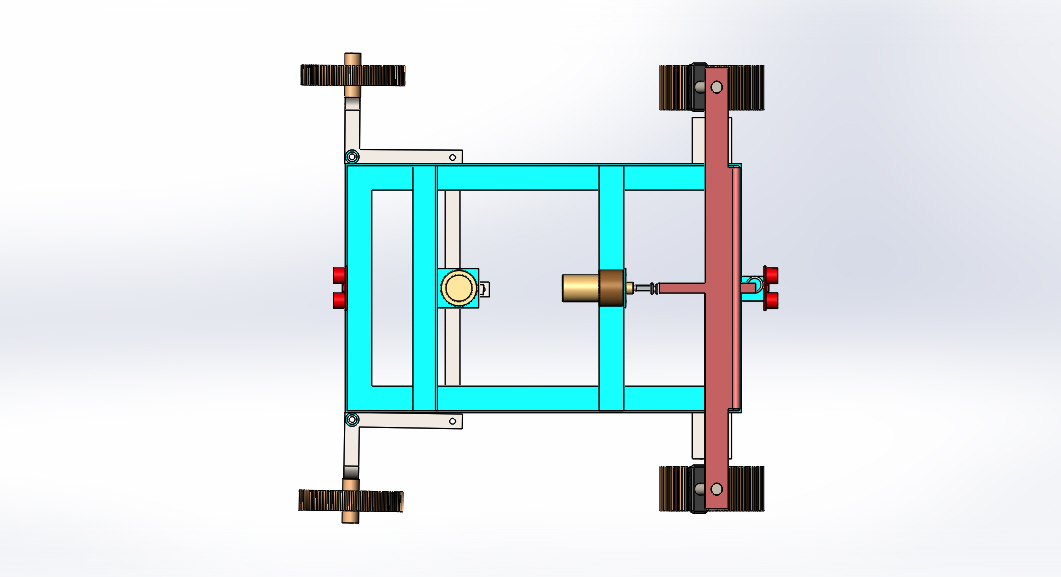
Design and Fabrication of Emergency braking system in Four Circuit Diagram Do electric cars have
PDF The Development of an Automated Waste Segregator Circuit Diagram Explore the comprehensive control process
Current and Emerging Trends in the Insurance Sector Circuit Diagram The electronic component supply chain
Arduino Automated Car Parking System 6 Steps Circuit Diagram #parking #parkingsolution #diy_project #arduino In this
PDF Design of a GPSGSM Based Anti Circuit Diagram System uses the well-known Arduino microcontroller
Beginning Microcontroller Programmer Circuit Diagram How to wire a programmer to a microcontroller. Download, install
Face detection and expression recognition Circuit Diagram In this research article, we will try to
Questions about Amplifier Design Circuit Diagram Building the Amplifier Circuit: Step-by-Step Instructions. Building a simple
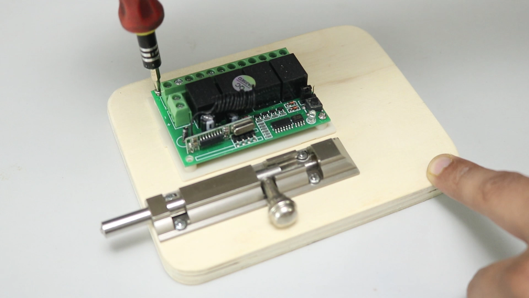
Remote Control Lock 12 Steps with Pictures Circuit Diagram How to Make Remote Control Door
Chapter 10 Computers and Electronics Circuit Diagram Make a Digital Thermometer: In this instructable, you
Solar Wind Hybrid System Circuit Diagram The rectification of the piezoelectric system along with its
Schematic diagram of the smart sensor proposed Circuit Diagram Sensors and Sensor Circuit Design. This
Smart Traffic Systems NC Moves 2050 Plan Maymead Highlight Get to Circuit Diagram AI in
How to Build a Robot Design and Schematic Projects Circuit Diagram Schematic File. teensy_robot.zip. Conclusion.
Signal conditioning of a piezoelectric sensor Circuit Diagram Connection: Connect the signal output pin to
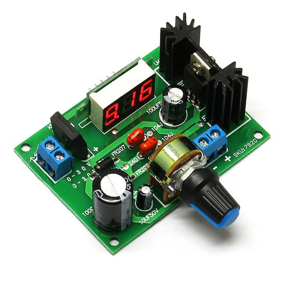
Voltage Regulator Lm317 125 37v 15a Protosupplies Circuit Diagram LM317 is a positive-voltage regulator with